An inverter converts direct current into alternating current, but its performance depends on more than switching devices. The Inverter Inductor stores and transfers energy, smooths current, and helps limit electrical noise. Its role changes with the inverter topology, switching frequency, power level, and control strategy. Small component, significant consequences.
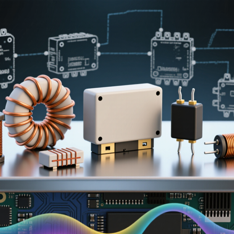
Common types include boost and buck inductors, which support voltage conversion, alongside filter inductors that reduce ripple at the output. Common-mode and differential-mode inductors address different forms of conducted noise. Coupled inductors combine magnetic windings to support particular circuit functions, while planar designs can suit compact layouts and automated assembly. These categories are not always mutually exclusive; names often describe a component’s purpose, construction, or both.
Choosing among them calls for practical checks, not just a label on a datasheet. Engineers compare inductance, saturation current, winding resistance, core losses, temperature rise, and available space. For example, a tightly packed inverter may benefit from a low-profile planar part, yet thermal limits can change that choice. There is no universal “best” type. Real operating conditions matter, and the ideal selection may look less obvious after measurement. This guide introduces the main inverter inductor types, explains where each is commonly used, and outlines the trade-offs that help designers make informed comparisons.
Core Designs Used in Inverter Inductors
An inverter inductor’s core shapes its size, losses, heat, and ability to handle current. The choice depends on switching frequency, ripple current, and cooling—not just rated power. The IEA PVPS Trends in Photovoltaic Applications 2024 report estimates that solar installations added about 447 GW worldwide in 2023. That growth makes efficient power conversion increasingly important, though it does not make one core design right for every inverter.
Laminated silicon steel suits lower-frequency, high-power applications. Its thin sheets limit eddy-current losses, but the core can be bulky. Ferrite offers lower losses at higher switching frequencies and is common in compact designs; however, saturation can become a concern under heavy current. Distributed-gap powder cores, including iron-based and alloy powders, handle DC bias well and can soften saturation. Amorphous and nanocrystalline alloys can reduce core loss in suitable designs, but cost and mechanical handling may complicate production. There is no perfect core. Engineers compare measured losses across the inverter’s actual frequency and temperature range.
Tips: Check the manufacturer’s loss curves and DC-bias data at your operating conditions. Then verify temperature rise in a representative test. A small sample can mislead; winding layout and airflow matter, too.
Representative frequency ranges where these core designs are commonly used in power magnetics. Ranges overlap and vary with core geometry, material grade, losses, and design conditions.
Ferrite is widely used in high-frequency inverters; powder cores provide distributed gaps for energy storage; nanocrystalline and amorphous alloys are used in high-performance designs. Laminated electrical steel is more typical of line-frequency and lower-frequency applications.
Ferrite-core inductors suit many inverter designs because ferrite limits eddy-current losses as switching frequency rises. Their high electrical resistivity helps keep core heating manageable, while compact cores can store and transfer energy in a small space. The trade-off is real: ferrite can saturate under excessive current, and its losses still depend on frequency, flux swing, temperature, and core geometry. Small details matter.
In a practical inverter, engineers compare measured core-loss curves with the expected waveform, not just a headline frequency rating. An air gap can increase energy storage, but it also creates local fringing fields that may heat nearby copper. IRENA’s Renewable Capacity Statistics 2024 reports 473 GW of renewable capacity additions in 2023, underscoring the growing role of power conversion equipment. That figure does not predict inductor demand directly, but it shows why efficient inverter components matter. Ferrite is not automatically the best choice; prototypes can reveal losses that a simplified calculation misses. For reliable selection, check temperature rise, saturation margin, winding layout, and performance across the full operating range.
What Are the Top Types of Inverter Inductors?
Powdered-Iron Inductors for Energy Storage
Powdered-iron inductors can suit energy-storage inverters that need to manage changing current without abrupt magnetic saturation. Their distributed air gaps help store energy across the core, while the powdered material can offer stable performance under demanding current conditions. In practice, core size, switching frequency, and ripple current all affect the result. A design that looks compact on paper may still run hot in a sealed enclosure. That part is easy to underestimate.
For a battery inverter, engineers should compare inductance, saturation behavior, core loss, and winding temperature at the expected operating point. Powdered iron is not automatically the best choice: its core losses may be higher than those of some alternatives at certain frequencies. Measure temperature and ripple current in the actual circuit, rather than relying only on a catalog value. One test setup may not reflect the final enclosure or cooling conditions. I would check that twice.
Tips: Check the inductor’s current rating at operating temperature, not just at room temperature. Leave room for airflow around the component, and inspect winding temperatures during sustained operation. If the measured heat differs from expectations, revisit the switching frequency and core selection before increasing the rating.
| Core Type | Core Structure | Energy-Storage Characteristics | Key Advantages | Trade-Offs | Typical Inverter Uses |
|---|---|---|---|---|---|
| Powdered iron | Ferromagnetic powder particles are insulated from one another and pressed into a core. The distributed gaps between particles reduce the need for a single large air gap. | Distributed-gap behavior supports energy storage and helps the inductor tolerate DC bias. Inductance still decreases as current and magnetic flux increase, depending on the core grade and design. | Often cost-effective; available in practical shapes such as toroids; can provide gradual inductance roll-off under increasing DC bias. | Core loss and temperature rise depend on frequency, flux swing, material grade, and waveform. It may require a larger core than a lower-loss material for some high-frequency designs. | DC-link chokes, boost and buck-boost stages, and other energy-storage or ripple-filtering positions where bias tolerance and cost matter. |
| Ferrite | A ceramic magnetic material, commonly used as a solid core; power-inductor designs may include a deliberate air gap to store energy. | Can offer low core loss at suitable switching frequencies. A gapped design stores energy, but the gap and core size must be chosen to meet DC-bias requirements. | Useful for high-frequency power conversion; broad range of material grades and core shapes. | Ferrite is comparatively brittle, and a gapped core can produce localized fringing fields and winding losses near the gap. | High-frequency inverter stages and compact converters when switching-frequency loss and component size are important. |
| Sendust (Fe-Si-Al) | An iron-silicon-aluminum powder core with distributed gaps formed by the insulated particles. | Distributed-gap construction supports energy storage and DC-bias operation. Performance varies with the selected grade and operating conditions. | Can offer a useful balance of core loss, bias performance, and core size in power-inductor applications. | Material cost and loss performance should be compared with alternatives at the actual switching frequency, flux swing, and temperature. | Energy-storage chokes and power-factor-correction or DC-DC stages where distributed-gap behavior is useful. |
| MPP (molypermalloy powder) | A distributed-gap powder core made from a nickel-iron-molybdenum alloy. | Designed for energy storage with stable inductance under DC bias; core loss and usable flux depend on the specific grade and design. | Can provide low core loss and good bias characteristics in demanding power-inductor applications. | Typically more expensive than many general-purpose powder-core options. | Compact, higher-performance energy-storage inductors where loss and inductance stability justify the material cost. |
| High-flux powder alloy | A distributed-gap powder core based primarily on an iron-nickel alloy. | Offers high saturation capability among common powder-core families, which can be helpful in high-current energy-storage designs. | Useful when high DC bias or high current is a major design constraint. | Usually costs more than standard powdered iron; core loss must be checked against the chosen grade and operating point. | High-current boost converters, DC-link chokes, and energy-storage stages requiring strong bias capability. |
| Nanocrystalline | A very thin-ribbon soft-magnetic alloy core, often formed as a wound or cut core; a gap may be added for energy storage. | Can provide high permeability and low loss in suitable applications. Energy-storage capability depends on the gap, core geometry, and DC-bias design. | Useful in designs seeking high magnetic performance and reduced losses over an appropriate frequency range. | Core handling, gap design, availability, and cost may be less straightforward than for common powdered-iron cores. | Selected high-performance inverter filters and power stages, subject to frequency, bias, and mechanical requirements. |
| Selection note: Compare core loss, DC-bias performance, temperature rise, winding loss, size, and cost at the intended frequency, current, ripple, and operating temperature. Material-family descriptions are general; actual performance depends on the specific core grade and design. | |||||
Air-core inductors can suit inverter stages where low magnetic loss and clean high-frequency behavior matter. They use no ferrite or iron core, so they avoid core saturation and hysteresis loss. A copper winding still warms under load. Measure it.
In a compact inverter, an air-core coil may handle fast switching without core-related distortion, but its magnetic field spreads beyond the winding. Nearby conductors can pick up noise. Spacing and shielding deserve careful attention, especially around current sensors and control circuits. The trade-off is real: removing the core reduces one loss source, not every loss source.
Demand for efficient conversion is growing alongside renewable generation. IRENA’s Renewable Capacity Statistics 2024 reports that global renewable capacity reached 3,870 GW in 2023, following a record 473 GW addition that year. That figure does not measure inductor demand, but it shows the expanding power-electronics landscape. In practice, designers should compare winding resistance, operating frequency, current ripple, and temperature rise under the intended load. An air-core design can be elegant on a schematic. It can also take more space than expected. Check the bench results.
Selecting an inverter inductor starts with the operating waveform, not its appearance. DC-link chokes reduce current ripple before power reaches the switching stage. Output filter inductors smooth pulse-width-modulated voltage for motors or grid-connected loads. Common-mode inductors target unwanted noise on paired conductors. Boost inductors store energy during voltage conversion. Each type handles a different electrical task.
Check the continuous current, peak current, switching frequency, and allowable temperature rise. The inductance must remain stable under DC bias. A core can saturate during a short overload. That moment may damage switches quickly. Ferrite cores suit higher-frequency filtering, while powdered cores can tolerate stronger energy storage. However, core losses vary with frequency and waveform. Measure them under realistic conditions, not only at room temperature.
Mechanical details matter too. Confirm creepage, clearance, insulation strength, and winding temperature. In practical testing, a quiet inductor can still run dangerously hot inside a sealed enclosure. Thermal imaging can expose this problem. Keep leads short to limit stray inductance and ringing. Also examine audible noise during light-load operation. A calculated inductance is only a starting point. Real systems include tolerances, aging, vibration, and unexpected transients. I would recheck the design after testing, because the first selection is rarely perfect.